Total harmonic distortion plus noise (THD+N) is a measure of the unintended harmonics and noise in the output signal of an audio device. It’s measured as the ratio of energy from the harmonics and noise relative to the energy from an input signal. Modern audio devices, such as audio interfaces, have relatively low levels of THD+N. Nevertheless, lower is better when comparing THD+N specifications, and in order to make like-for-like comparisons, it’s important to know the parameters used in making the THD+N measurements.
In this article we’ll look at:
- What is harmonic distortion and what are its effects?
- How harmonic distortion is measured in audio systems (THD+N)
- Example audio interface THD+N specifications
- The acceptable range of THD+N in audio interfaces
- Conclusion
- FAQs
What is harmonic distortion and what are its effects?
Electronic devices used in audio production systems modify input signals in various ways—that’s exactly what we want them to do. Unfortunately, there are unwanted side effects that can alter the output signals in undesired ways, and this is referred to as distortion.
Harmonic distortion
Harmonic distortion occurs when unwanted harmonics of the input signal develop at the output. A signal’s harmonics are integer (i.e., whole number) multiples of the frequency of the input signal.
One way to understand harmonic distortion is in terms of non-linearities.
In a linear electronic system, the input signal is faithfully reproduced at the output, i.e., the output signal waveform is identical to the input waveform. Non-linearities, however, introduce deviations in the output waveform.
Harmonic distortion is an example of unwanted non-linear outputs for a given input signal.
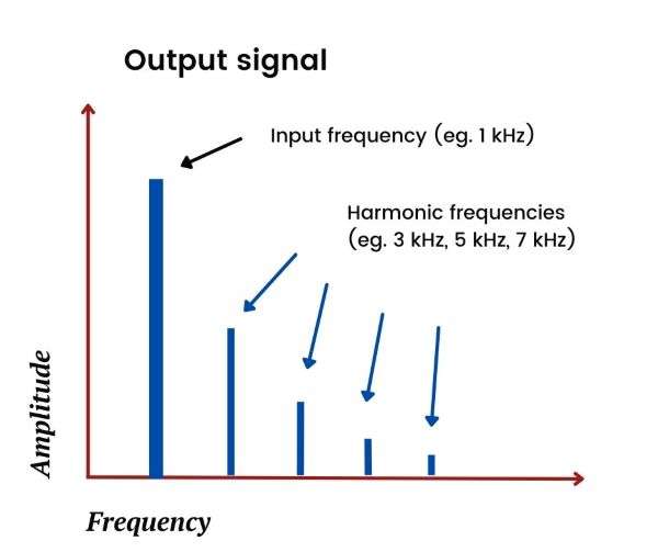
You can see what harmonic distortion looks like by measuring the amplitude of output frequencies relative to input frequencies—harmonic distortion results in positive amplitudes at one or more output frequencies that are multiples of the input frequency, as shown below:
Intermodulation distortion
If we’re testing for harmonic distortion, it’s common practice to use a simple and well-defined input signal, such as a 1 kHz pure sine wave. Harmonic distortion shows up as output signals with (noticeable) amplitudes at the harmonics of this sine wave, eg. 3 kHz, 5 kHz, etc.
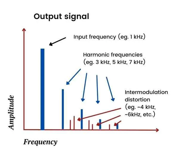
If we input two signals rather than one, say a 1 kHz and a 4 kHz signal, then the harmonics that could appear at the output would be:
- Harmonics of the 1 kHz signal, e.g., 3 kHz and 5 kHz
- Harmonics of the 4 kHz signal, e.g., 8 kHz and 12 kHz
- Harmonics of the “interaction” between these two signals, i.e., the sum and differences of the frequencies of the input signals and their harmonics—this is referred to as intermodulation distortion
So, inputting two or more signals can add to the possible harmonic distortion at the output, not only due to the input signals themselves but also due to their interactions.
Most input signals in an audio production environment are a mixture of several frequencies at different levels of amplitude (loudness), so the possible harmonic distortion for audio signals can be quite complex due to intermodulation distortion.
This is one of the reasons why harmonic distortion in audio systems can be more challenging than in other systems, such as electrical power systems, that typically operate at a single frequency.
Intermodulation distortion is shown below:
How harmonic distortion is generated
We’ve already seen how we can think of harmonics as being a result of non-linearities in electronic systems. But, why do harmonics develop in electronic systems at all?
As it happens, these non-linearities arise due to the inherent properties of certain electronic components that make up the devices found in electronic systems.
All electronic components produce noise, but some components generate non-linear disturbances that lead to harmonic distortion. This is particularly true for electronic transducers that convert one form of energy to another, e.g., converting movement in a microphone diaphragm into electrical signals.
Active electronic components, such as the FET or MOSFET transistors found in amplifiers, also generate non-linearities. This is because they don’t amplify all points of an input signal equally. This leads to an unequal, or non-linear, reproduction at the output signal.
The type of amplifier configuration—class A, class AB, or class B, for instance—also affects the degree of non-linearity in amplifier output signals.
In audio production, electronic devices such as audio interfaces contain several components that lead to non-linearities in the signal path between input and output—all of these combine to produce varying degrees of harmonic distortion.
The effects of harmonic distortion in audio
Audio systems typically produce sounds that humans can hear and interpret. This means that the output of an audio system is heard in a subjective way, and may be perceived differently by different people.
While harmonic distortion is generally undesirable in systems such as electrical power networks, as it can lead to inefficiencies and damage, it is sometimes desirable in audio systems.
Harmonic distortion changes the character and timbre of a sound (the input signal) and can create richer and more charismatic tones at the output.
Classic examples of using distortion are the characteristic sounds of 1950s electric guitar by musicians such as Chuck Berry and Jimi Hendrix.
But while distortion has a role to play in audio production from an artistic perspective, it’s highly subjective and needs to be carefully managed. When distortion is the desired outcome of audio production, it’s intentionally added through effects processing or by using amplifiers.
More generally, the goal of audio production devices is to keep harmonic distortion to a minimum as it can detract from the quality and character of the output sound.
Audio interfaces are no exception, and the best interfaces are designed to keep levels of harmonic distortion as low as possible.
In a well-designed audio production system, therefore, harmonic distortion should only be added when intended, and not through the unwanted effects of various devices in the system.
How harmonic distortion is measured in audio systems (THD+N)
Two of the most widely used methods for measuring harmonic distortion in audio systems are Total Harmonic Distortion (THD) and Total Harmonic Distortion plus Noise (THD+N).
While the concepts underlying these are similar, in practice THD+N is easier to measure than THD.
THD+N is also a more useful measure than the total harmonic distortion calculation for audio applications, as it captures additional sources of noise other than harmonic distortion (such as hum, interference, and white noise). As a result, THD+N (rather than THD) is often quoted in the specifications for audio devices such as audio interfaces and amplifiers.
THD vs THD+N
THD is a measure of the energy of all of the harmonics (or a selected few) generated by a system relative to the input signal.
THD+N, on the other hand, is a measure of the energy of all of the harmonics and all of the noise generated by a system relative to the input signal. THD+N values are almost always higher than THD values, as it includes noise in its calculation in addition to harmonics.
To measure THD, the input signal and its harmonics need to be separately identified and included in the calculation. This involves a series of measurements—one at each harmonic of the input signal—to ensure that other sources of noise are not included in the calculation.
In contrast, calculating THD+N involves only two measurements—the total energy of the output signal, and the energy at the input frequency—the THD+N is simply based on the difference between these two, ie. “everything that’s left after removing the input signal”.
As THD+N uses a simpler approach in its calculation, it’s much easier to measure in practice compared to THD.
As mentioned, THD+N is also more commonly used for audio device specifications.
Some audio devices, however, particularly electro-acoustic devices such as loudspeakers and microphones, tend to use THD rather than THD+N. This is due to the relatively high levels of ambient noise that may be present when making acoustic measurements for these devices.
For audio devices that aren’t electro-acoustic in nature, such as amplifiers and audio interfaces, THD+N is the preferred measure—ambient noise is less of an issue for these devices. Rather, the levels of electronic (and magnetic) noise produced by these devices are important for understanding their fidelity.
Let’s take a closer look at calculating THD+N.
How to calculate THD+N
A typical method for measuring THD+N of an electronic audio device is as follows:
- Apply a pure sine wave with a well-defined frequency, say 1 kHz, as the input signal to the device
- Measure the energy of the total output signal of the device—energy is usually measured using root-mean-square (RMS) calculations
- Measure the energy of the input frequency (e.g., 1 kHz) at the output—the input frequency can be isolated at the output by using suitable frequency filters
- Find the difference in the energies of the input frequency and the total output signal—this represents the energy of all the harmonics and noise in the system, excluding the input frequency
- Compare the energies measured in steps 3 and 4, i.e., the energy of all the harmonics and noise in the system compared with the energy of the input frequency—this comparison is often specified in percentage terms (%)
The formula below illustrates what the THD+N calculation represents:
THD + N = [ √( vH12 + vH22 + … + vHn2) + Noise ] / vI
Where,
- vH1 to vHn are the 1st to nth harmonics of the input frequency, and √( vH12 + vH22 + … + vHn2) is the total energy (RMS) of the harmonics
- Noise is the energy (RMS) of the total noise at the output in addition to the harmonics
- vI is the energy (RMS) of the input frequency
Keep in mind that the above formula is only a representation of the THD+N measurement process—the actual process doesn’t require measuring each individual harmonic separately.
Rather, as outlined above, only the total energy at the output and the energy of the input frequency need to be measured (the THD+N calculation is derived from these measurements).
Sine waves are a good choice of input signal for measuring THD+N as they have all of their energy concentrated at a single frequency (e.g., 1 kHz). This makes it easy to isolate the input frequency and to know what frequencies the harmonics will be at.
THD+N specifications
As mentioned, THD+N specifications for audio devices are often expressed as a percentage.
A THD+N figure of 0.01%, for instance, means that the energy of all the harmonics and noise (at the output) is 0.01% of the energy of the input frequency (at the output).
But, there’s more that goes into a proper specification of THD+N.
From the measurement process outlined earlier, we know that there are a number of elements to calculating THD+N. For a THD+N specification to be meaningful, therefore, the parameters used in the measurement process should be stated.
A meaningful specification of THD+N should include parameters such as:
- The frequency of the input signal
- The level (amplitude) of the input signal
- The measurement bandwidth
- The gain applied
Let’s look at a couple of real-world examples to see how THD+N specifications work in practice.
Example audio interface THD+N specifications
The following examples of THD+N specifications are for two popular audio interfaces:
- The Solid State Logic SSL 2 plus—a budget-friendly USB audio interface from an acclaimed manufacturer of analog and digital mixing consoles
- PreSonus Studio 24c—a popular and affordable audio interface that’s a favorite among home studios
The THD-N specifications provided in the user manuals for these two audio interfaces are shown below.
| Specification Parameter | SSL 2+ | Studio 24c |
|---|---|---|
| THD+N | < 0.0015%, < 0.005% | 0.005% |
| Frequency of input signal | 1 kHz | 1 kHz |
| Level of input signal | -8 dBFS, -1 dBFS | -1 dBFS |
| Measurement bandwidth | 20 Hz to 20 kHz | not specified |
| Gain applied | not specified | Min gain |
THD+N specifications are provided for a range of inputs and outputs in audio interfaces—line inputs, instrument inputs, microphone inputs, and monitor outputs, amongst others—for the purposes of illustration, however, only the line input specifications are shown above.
The THD+N specifications for both interfaces are quoted as percentages—these indicate the relative size of the energy of the harmonics and noise at the output compared to the energy of the input frequency.
While both interfaces follow good practice in providing parameters of the test conditions, each is missing a parameter—the gain is missing for the SSL 2+ and the bandwidth is missing for the 24c.
The SSL 2+ offers some extra information, though, as it provides two specifications—one with an input level of -8 dBFS and another at -1 dBFS. The THD+N is different for these two levels, being lower for the smaller input level (<0.0015% at -8 dBFS vs <0.005% at -1 dBFS).
These results are not surprising—harmonic distortion is known to increase with larger signal levels in many systems, particularly as the signal level approaches its maximum. At -1 dBFS, the input signal is 1 dB below its maximum, resulting in more harmonic distortion (THD+N of 0.005%) relative to when the signal is 8 dB below its maximum (THD+N of 0.0015% at -8 dBFS).
Only the SSL 2+ provides a measurement bandwidth. Although not provided for the Studio 24c, it’s likely that the measurement bandwidth is similar, i.e., 20 Hz to 20 kHz. This is quite typical of THD+N measurement for audio interfaces.
Some audio interfaces, however, include a much wider bandwidth, e.g., 20 Hz to 80 kHz.
Why is this necessary? After all, the range of human hearing is only around 20 Hz to 20 kHz.
The reason is that when the measurement bandwidth is limited to 20 kHz, any harmonics of higher frequencies aren’t captured. The third harmonic of 10 kHz, for instance, is 30 kHz, and the second harmonic of 12 kHz is 24 kHz.
In practice, however, lower-frequency harmonics tend to have more energy than higher-frequency harmonics.
What’s more, human hearing is less sensitive to frequencies outside of a range of 1 kHz to 8 kHz (this is the principle underlying A-weighted dB measurements.
So, a measurement bandwidth of 20 Hz to 20 kHz is considered acceptable for most situations.
Finally, the gain applied to the input signal hasn’t been specified for the SSL 2+ and was applied at a “minimum” for the Studio 24c.
So, while it seems a little confusing at first, the specification parameters for THD+N measurements are important for making like-for-like comparisons between audio interfaces.
Without the full range of parameters, it’s hard to know whether one interface’s THD+N measures are actually better or worse than another’s.
The acceptable range of THD+N in audio interfaces
Having seen a couple of examples of THD+N measurements, a natural question to ask is: What’s an acceptable range for THD+N specifications?
Before looking at an answer to this question, there are three points worth noting about harmonic distortion and THD+N measurements in audio devices:
1. THD+N specifications are limited in scope
THD+N specifications are based on specific measurement parameters that may not translate to real-world usage—the THD+N value for a pure sine wave at 1 kHz, for instance, grossly understates the possible range of frequencies and complex harmonics that may be generated by a piece of music. Also, different types of musical sounds may have quite different harmonics.
2. THD+N specifications can be quite different when using different measurement parameters
We saw an example of this with the SSL 2+ specifications—the THD+N specification varied considerably depending on the level of the input signal applied. So, it’s important to make comparisons based on like-for-like measurement parameters.
3. Harmonic distortion is interpreted subjectively by humans
We briefly discussed this with the examples of “artistic distortion” used by musicians such as Berry and Hendrix—an absolute value of THD+N doesn’t tell you the whole story. The context of how and why the output sound of an audio device is intended to be used is relevant when evaluating harmonic distortion.
Nevertheless, for the purposes of devices such as audio interfaces, generally speaking, lower is better for THD+N.
With this in mind, an acceptable range for THD+N is 0.01% or lower.
Why is THD+N < 0.01% an acceptable range?
Noting the points above, this is clearly a subjective answer.
To understand why this range may be considered acceptable, let’s first look at how different THD+N percentage values translate to relative loudness (measured using dB SPL), and what levels of loudness in distortion are acceptable for human hearing.
Converting THD+N percentages to dB
A simple way of interpreting percentage THD+N specifications is to note that each ten-fold decrease in THD+N represents a 20 dB reduction in distortion levels (loudness) relative to the input signal. This is a consequence of how dB is calculated in audio applications.
In fact, some audio interfaces specify their THD+N in dB, rather than using percentages.
A THD+N value of 1%, for instance, translates to distortion levels that are 40 dB below the input signal’s level, and a THD+N value of 0.1% translates to distortion that’s 60 dB below the input signal.
So, with all else equal, a THD+N of 0.001% (distortion at 100 dB below the input signal), is better than a THD+N of 0.01% (distortion at 80 dB below the input signal).
Acceptable levels of distortion
In the audio interface THD+N specifications that we looked at earlier, the THD+N values were 0.005% (for a -1 dBFS signal, i.e., close to the maximum possible signal without clipping). This means that the distortion levels are approximately 86 dB below (i.e., less loud than) the signal level—these are very low levels of distortion.
To put this in context, the sound levels associated with a busy street are around 80 dB SPL, and for a pneumatic drill, it’s around 90 dB SPL.
So, for our example audio interfaces, the distortion levels would be inaudible relative to the sound levels of a busy street (since 80 dB SPL – 86 dB is less than 0 dB SPL). And, for the sound levels of a pneumatic drill, the distortion would only be a few dB (since 90 dB SPL – 86 dB SPL is only 4 dB SPL).
In other words, you would need to produce an output sound louder than a busy street before you would even hear the distortion coming from the audio interfaces that we looked at.
Coming back to our acceptable range of THD+N of 0.01% or lower, this translates to 80 dB below an input signal’s level—distortion at this level would be inaudible relative to sound levels lower than of a busy street.
As it happens, most modern audio interfaces have very low THD+N levels and are not likely to add meaningful distortion to the output sound.
Other sources of interference—from external disturbances, damaged connecting cables, poor acoustic conditions, etc.—are more likely to detract from sound quality than harmonic (and noise) distortion in an interface.
Conclusion
Total harmonic distortion plus noise (THD+N) in an audio device is a measure of the unintended harmonics and noise produced by the device.
THD+N is calculated as the total energy level of the harmonics and noise at the output of a device relative to the energy level of the input frequency. It’s often expressed in percentage terms (but sometimes in dB).
To properly quote THD+N specifications, the parameters of the measurement should be stated.
These parameters include the frequency and level of the input signal, the bandwidth applied, and the gain applied. Without knowing these, it’s difficult to make like-for-like comparisons between different THD+N specifications.
Most modern interfaces produce low levels of harmonic distortion based on their THD+N specifications—often in the range of 0.005% or lower. This translates to inaudible distortion when compared with sounds that have a loudness similar to a busy street.
Although subjective, THD+N of 0.01% or lower is acceptable for devices such as audio interfaces—at these levels, other sources of noise or interference are likely to dominate those coming from harmonic distortion.
FAQs
What is THD?
THD stands for Total Harmonic Distortion and is a measure of the energy of all of the harmonics (or a selected few) generated by a system relative to the input signal.
What is THD in audio?
THD, or Total Harmonic Distortion, in audio is a measure of the distortion (i.e., energy) from the harmonics present in an audio signal when compared to the original pure sinusoidal signal.
What is THD+N?
THD+N stands for Total Harmonic Distortion plus Noise and is a measure of the energy of all of the harmonics and all of the noise generated by a system relative to the input signal.
What is the significance of THD measurement in audio?
THD measurement provides valuable information about the quality of audio equipment. Lower THD values generally indicate lower levels of distortion and better audio fidelity.
How is THD+N expressed?
THD+N is typically expressed as a percentage or ratio. For example, a THD+N of 0.01% means that the energy of a signal’s output harmonics and noise is 0.01% of the energy of the signal’s input.