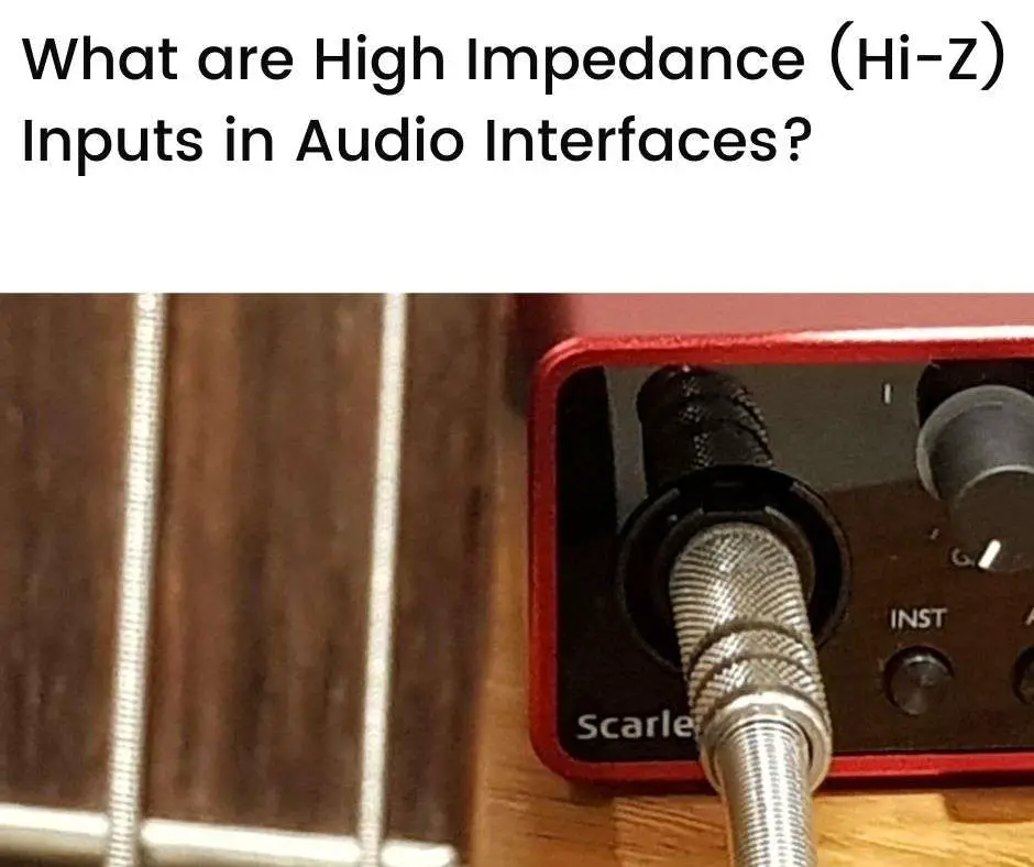
High impedance (Hi-Z) inputs in audio interfaces connect instruments that have, in themselves, a relatively high impedance. Hi-Z inputs allow a good degree of voltage transfer from these connected instruments. This is especially useful given the typically low signal output levels from such instruments. Many audio interfaces have Hi-Z inputs that offer very high impedances for this purpose.
In this article we’ll look at:
- What is impedance?
- High impedance vs low impedance
- Example high impedance (Hi-Z) inputs in audio interfaces
- Conclusion
What is impedance?
In electronic circuits, a basic relationship exists between voltage, current, and resistance. These are related according to Ohm’s law, which can be expressed as:
V = I x R
Where, V is the voltage across a conductor (ie. a material that conducts electricity, such as a copper wire or purpose-built resistor), I is the current that flows through it, and R is the resistance of the conductor (ie. the extent to which the conductor “resists” current flow).
Voltage is measured in volts (V), current is measured in amps (A), and resistance is measured in ohms (Ω).
Ohm’s law applied to alternating current (AC)
The above equation for Ohm’s law applies for direct current (DC) circuits. When it comes to alternating current (AC) circuits, the picture becomes a bit more complicated.
AC is the type of current that’s used in most power supply networks around the world. They are the type of current found in most households and commercial enterprises.
AC is also the type of current that flows through the components of audio production equipment. This is because AC conveys variations in voltage (and current) that carry information about audio signals—it varies in a way that depicts the variations in sound waves.
The concept of Ohm’s law can also be used for alternating current, as follows:
V = I x Z
Here, V is the AC voltage across a conductor, I is the alternating current flowing through it, and Z is the “AC resistance” of the conductor which is referred to as impedance.
Voltage, current, and impedance are measured in the same units for AC as they are for DC, ie. voltage, amps, and ohms.
Resistance vs impedance
The impedance of a circuit indicates the “degree of resistance” that the circuit has to an alternating current flowing in it.
But why is impedance different from resistance?
Under DC, there is no frequency associated with a current (ie. the frequency of DC is zero). Under AC, a current fluctuates at one (or more) frequencies—the way in which electronic circuits respond to frequencies of current (or voltage) is the reason why resistance differs to impedance.
Resistance applies to DC, ie. at zero frequency of current.
Impedance captures the way in which circuits respond to different frequencies of current.
Reactive electronic components
Most circuits contain resistors, capacitors, and inductors. These are all passive and linear components, meaning that the output amplitude of a waveform passing through them will be proportionate to the input amplitude.
Capacitors and inductors, however, respond differently to AC vs DC, whereas resistors do not.
For capacitors and inductors, the resistance is not equal to the impedance. For resistors, the resistance and impedance are the same.
Capacitors and inductors are known as reactive components for this reason—they react differently to currents of different frequencies.
Capacitors and inductors are also different to each other (yet similar), with capacitors being responsive to voltage changes and inductors being responsive to current changes.
They also have the property of phase shifting between the voltage and current waveforms flowing through them:
- In a purely capacitive circuit, the voltage waveform lags the current waveform by a quarter of a cycle (ie. 90 degrees or π/2)
- In a purely inductive circuit, the current waveform lags the voltage waveform by a quarter of a cycle (ie. 90 degrees or π/2)
A comparison between resistors, capacitors, and inductors is shown in the table below:
| Circuit Component | Resistors | Capacitors | Inductors |
|---|---|---|---|
| Description | Conductors for which the current flowing through it is proportional to the voltage across it | Components for which the rate of voltage change is proportional to the current flowing through it | Components for which the rate of current change is proportional to the voltage applied across it |
| Essential property | Opposes (ie. “resists”) the flow of current | Opposes the change in voltage, and stores energy in an electric field | Opposes the change in current, and stores energy in a magnetic field |
| Common usage | DC or AC circuits | AC circuits | AC circuits |
| Linear component? | Yes | Yes | Yes |
| Responds differently for DV vs AC? | No | Yes | Yes |
| Phase difference between voltage and current signal | None | Voltage lags current by π/2 | Current lags voltage by π/2 |
Impedance and reactance
As mentioned, capacitors and inductors are referred to as reactive components due to their behavior under AC. From this, we can think of impedance in the following way:
Impedance (Z) = resistance (R) + reactance (X)
Where, the reactance is the contribution to impedance from any capacitive or inductive elements in a circuit under AC. It is often abbreviated as X.
Under DC, the reactance of a circuit will be zero and its impedance will simply be the same as (ie. entirely caused by) its resistance.
Under an alternating current, a circuit’s impedance will be due to both the resistive and reactive properties of the circuit.
High impedance vs low impedance
Let’s now consider the relative impedance of devices when they connect to each other.
Under DC, the resistance of different circuit elements affects the way that current flows through, and voltage forms across, a circuit. Similarly, under AC, the impedance of circuit elements affects the flow of voltage and current in a circuit.
In an audio production environment, various devices connect with each other to allow a signal to pass through a workflow. An example of this is when an instrument (like a guitar) connects to an audio interface.
You can think of such connections as the joining of two electronic circuits to form a combined circuit. When this happens, the impedance of each of the circuits being combined will determine how current and voltage develop in the combined circuit.
So, when two audio devices connect with each other, the relative difference in their impedance matters.
The degree to which one device has, say, a high impedance relative to another device with a low impedance, or vice versa, makes a difference in how current and voltage behave when the devices are connected.
Connecting audio devices
Let’s look closer at the situation where one device connects to another device. We’ll refer to the connecting device as the source device, and the device being connected to as the input device.
An example of this is when an electric guitar (source device) connects to an audio interface (input device).
Consider the impedance of the source device—source impedance—relative to the impedance of the input device—input impedance. There are three general possibilities:
1. Source impedance high relative to the input impedance
When the source impedance is high relative to the input impedance, due to the voltage division effect, a large proportion of the voltage coming from the source will remain across the source and not across the input device.
Let’s look at an example:
- Source impedance of 1,000 Ω
- Input impedance of 1 Ω
If we have a 10 V source signal, then the input voltage will be:
Input voltage = 10 V x [1 Ω / (1,000 Ω + 1 Ω)]
= 0.00999 V
= 9.99 mV
So, of the 10 V being applied at the source, less than 1-thousandth of it transfers to the input.
Let’s also check the current drawn by the connected devices (using V = I x Z):
Current = total voltage across devices / total impedance of devices
= 10 V / (1 Ω + 1,000 Ω)
= 0.00999 A
= 9.99 mA
Keep in mind that the relationship V = I x Z holds for each device:
Source current = { voltage across source device } / impedance of source device
= { 10 V x [1,000 Ω / (1,000 Ω + 1 Ω)] } / 1,000 Ω
= 9.99 mA
Input current = voltage across input device / impedance of input device
= 9.99 mV (calculated above) / 1 Ω
= 9.99 mA
This makes sense—the current flowing through each device, and the connected devices, must be the same since they are connected in series.
2. Source impedance the same as the input impedance
By voltage division, we can see that in this case, an equally shared voltage is applied across the source and input.
For example:
- Source impedance of 1,000 Ω
- Input impedance of 1,000 Ω
Again, if we have a 10 V source signal, then the input voltage will be:
Input voltage = 10 V x [1,000 Ω / (1,000 Ω + 1,000 Ω)]
= 5 V
When the source and input impedances are equal in connected devices, this is referred to as impedance matching. Although only a fraction of the voltage is transferred, impedance matching allows for the maximum transfer of power.
3. Source impedance low relative to the input impedance
When the source impedance is low relative to the input impedance, again due to voltage division, a large proportion of the voltage coming from the source will transfer across the input device, and not remain with the source.
For example:
- Source impedance of 1 Ω
- Input impedance of 1,000 Ω
Again, if we have a 10 V source signal, then the input voltage will be:
Input voltage = 10 V x [1,000 Ω / (1 Ω + 1,000 Ω)]
= 9.99 V
So, of the 10 V being applied at the source, in this case, the vast majority of it transfers to the input.
Connecting instruments to audio interfaces
When it comes to connecting instruments—like electric guitars—to audio interfaces, the signal coming from the instruments (source signal) is usually quite small.
More importantly, electric guitar pickups have a high impedance, typically around 5-10 kΩ.
So, when connecting an electric guitar to an audio interface, the source impedance is high.
What does this mean in terms of the connection possibilities discussed above?
If we want to transfer a sufficient amount of the signal (voltage) coming from the electric guitar, then we need to have a high input impedance relative to the source impedance—this suggests the third connection approach outlined above.
For this reason, the input impedances for instruments in audio interfaces are very high—typically around 500 kΩ to 2MΩ. This is much higher than the 5-10 kΩ source impedance coming from instruments like electric guitars.
The relatively high instrument-input impedances on audio interfaces are often referred to as high impedance inputs or Hi-Z inputs.
As a “rule of thumb”, equipment manufacturers try to make Hi-Z input impedances at least 10 times the typically expected source impedance—this ensures a minimum level of (sufficient) voltage transfer from the source device to the input device.
Another benefit of having a high input impedance is due to the frequency response across the connection—relatively low input impedances can result in a diminished transfer of higher-end frequencies for instrument connections. A high input impedance helps to transfer frequencies more faithfully across the connection.
Example high impedance (Hi-Z) inputs in audio interfaces
Let’s now look at the instrument input impedance specs—high impedance, or Hi-Z, inputs—for a range of popular audio interfaces. This is shown in the table below:
| Audio Interface | Hi-Z Specs |
|---|---|
| Universal Audio Apollo Twin Mark II | High impedance instrument input: 1 MΩ |
| Arturia Minifuse 2 | High impedance circuits can be activated for instrument inputs: 1.1 MΩ |
| Solid State Logic SSL 2+ | High impedance switch for instrument inputs: 1 MΩ |
| MOTU UltraLite MK5 | Instrument (TRS) inputs: 1 MΩ (unbalanced) |
| PreSonus Studio 24c | High impedance instrument input: 750 kΩ |
| Focusrite Scarlett 2i2 | High impedance instrument input: 1.5 MΩ |
You’ll notice that the Hi-Z input impedances range from 750 kΩ to 1.5 MΩ for the interfaces shown above.
Let’s see how these inputs help transfer audio signals from a typical guitar source.
Consider an electric guitar with an impedance of 10 kΩ that generates an average voltage of 100 mV.
Using the principle of voltage division, we can calculate the voltage transferred across the input of the first audio interface shown in the above table (ie. the Universal Audio Apollo Twin Mark II with a 1 MΩ input impedance):
Input voltage = 100 mV x [1 MΩ / (1 MΩ + 10 kΩ)] = 99 mV
So, due to the high input impedance of the interface’s instrument input, 99% of the source voltage is transferred across the input.
We can, similarly, calculate the voltage transfer of the other interfaces in the above table for the same example source input (ie. 100 mV with 10 kΩ impedance)—this is shown in the table below:
| Audio Interface | Hi-Z Input Impedance | Voltage Transfer Across Input |
|---|---|---|
| Universal Audio Apollo Twin Mark II | 1 MΩ | 99.0% [= 100 mV x [1 MΩ / (1 MΩ + 10 kΩ)] = 99.0 mV, which is 99.0% of 100 mV] |
| Arturua Minifuse 2 | 1.1 MΩ | 99.1% |
| Solid State Logic SSL 2+ | 1 MΩ | 99.0% |
| MOTU UltraLite MK5 | 1 MΩ | 99.0% |
| PreSonus Studio 24c | 750 kΩ | 98.7% |
| Focusrite Scarlett 2i2 | 1.5 MΩ | 99.3% |
We can see that all of the audio interfaces have very high voltage transfers—around 99% or higher—thanks to their Hi-Z inputs.
As a check, let’s see what happens if we connect our guitar to an audio interface using a “standard” input rather than a Hi-Z input.
The Universal Audio Apollo Twin Mark II has a line input impedance of 10 kΩ—this is used for accepting higher-level signals from connected devices such as electronic synthesizers.
What would the voltage transfer be if we connected our example guitar to the line input of the Apollo Twin interface? In this case:
Line input voltage = 100 mV x [10 kΩ / (10 kΩ + 10 kΩ)] = 50 mV
So, the voltage transfer across the line input if we connected our example guitar would only be 50% (=50 mV/100 mV, in %). In other words, half of the (already low) input signal coming from the guitar would be “wasted” from an audio workflow perspective.
There may be additional drawbacks as well, such as an unfavorable frequency transfer, as mentioned earlier.
The Hi-Z inputs on audio interfaces, therefore, play an important role in allowing relatively high impedance, low-signal devices, such as electric guitars, to connect effectively to the audio workflow.
Conclusion
Impedance applies to alternating currents (AC) and is analogous to resistance, which applies to both direct currents (DC) and AC.
Impedance arises in capacitive and inductive circuit components. These have impedances that are related to the frequency of an AC signal and have a zero impedance for DC signals.
When audio devices are connected, the relative difference in their impedances will determine the degree of voltage transfer across the connection. For a good transfer from a source to an input connection, the input impedance should be much higher than the source impedance.
Many audio interfaces offer high impedance (Hi-Z) input connections. This is to ensure that a good degree of voltage transfers when connecting to instruments, such as electric guitars, that have relatively high source impedances.
The Hi-Z inputs found on popular audio interfaces offer impedances of around 750 kΩ to 1.5 MΩ. When connecting to instruments with typical impedances of 10 kΩ, a very high degree (99%) of voltage transfer can occur across Hi-Z connections.
Hi-Z inputs on audio interfaces, therefore, allow instruments such as electric guitars to connect directly, and effectively, to the audio workflow. This reduces the need for additional stages (such as pre-amplification) that may add complexity or unwanted noise to the workflow.